PWM and Analog Input Using TinyGo on Arduino Uno
This time with TinyGo I'm working with UART, PWM, ADC, and more! The goal is to make a controllable LED with the analog input pin on the Uno.


This time with TinyGo I'm working with UART, PWM, ADC, and more! The goal is to make a controllable LED with the analog input pin on the Uno.
This is interesting because the control dial (a potentiometer) is a separate circuit than the LED output:
Let's dig into the process that got us to this point!
(Final code is at the bottom).
Fiddling with UART and ADC Using TinyGo to Get Analog Input
No solution springs fully formed from someone's mind. Development is an iterative process.
In this case, I needed to learn how to get analog input in TinyGo. The documentation was super unclear, so I decided to "fiddle around" and see what came of it.
Here's my first attempt, using a potentiometer to split a 5V source, and dialling it up or down to change the voltage reading:
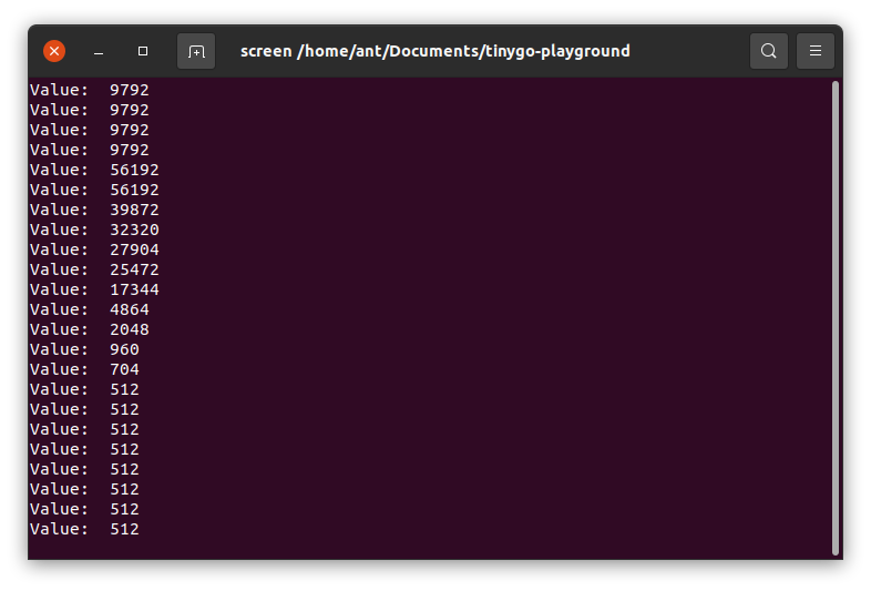
There's a lot going on here to unpack. First, I'm reading the voltage using ADC (analog to digital converter) inputs. Second, I'm able to debug the value I'm getting easily by using the println() method in TinyGo to print serial data to UART. I then read that serial data using screen on my USB-connected laptop.
The ADC value ranges from 0 to 65,535 (aka 0xffff for those familiar with hexadecimal). It's a 16-bit unsigned integer. In my case with the real-world voltage divider, I could neither top it out nor bottom it out – I could hit 56k and 512 but not 65.5k or 0. That's fine! The real world isn't perfect, after all.
ADC values also allegedly have only 10-bits of precision, so the last 6 bits are zeroed out. It just means that the jumps between discrete values returned via ADC will be in 6-bit jumps. 6 bits is 64 in decimal, which lines up with what we see in the debugging values: 512 is a multiple of 64. 704 is 192 more than 512, and is also a multiple of 64, and so on.
With UART, I'm easily able to see what's going on by debugging with prints. I can view the serial output (and send input) by using screen on Ubuntu:
screen /dev/ttyACM0 9600
ttyACM0 is the device port where my Uno is plugged in at, and 9600 is the baud rate.
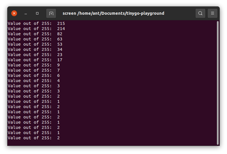
Since I figured out how to debug and get ADC values, the next step is to normalise them into floats between 0 and 1.0, which I can then multiply by 255 to map to the range 0 - 256:
The code for this is as follows:
package main

import (
    "machine"
    "time"
)

func main() {
    machine.InitADC() // init the machine's ADC subsystem

    input0 := machine.ADC{machine.ADC0}

    pwm := machine.Timer2
    led := machine.D11
    err := pwm.Configure(machine.PWMConfig{})
    if err != nil{println("PWM Config Error: ", err.Error())}

    ch, err := pwm.Channel(led)
    if err != nil{println("PWM Channel Error: ", err.Error())}
    for {
        inputValue := input0.Get()
        normal := normaliseInput(inputValue)
        println("Value out of 255: ", uint16(normal * 255))
        pwm.Set(ch, pwm.Top()/uint32(normal * 255))
        delayMilliseconds(1000)
    }
}

func normaliseInput(inputValue uint16) float32 {
    return float32(inputValue) / float32(0xffff) // ADC ranges from 0..0xffff
}

func delayMilliseconds(t int64) {
    time.Sleep(time.Duration(1000000 * t))
}
Without delving too deeply into it, notice that I've set up a pulse-width modulation channel on digital pin 11. This is used to dim an LED via PWM based on the analog voltage we read on ADC0 and normalise.
Basically: the higher the voltage we read, the lower the duty cycle is for the LED. Thus, the dimmer the LED grows.
This is cool because it's a different way to control an LED than most electrical students begin with. The potentiometer is a completely separate circuit from the LED, and in fact could just as easily be replaced by a rotary sensor.
The LED is not current limited or voltage modulated – it's PWM, so the pin 11 output is cycling between full voltage and ground frequently based on the timer of the Uno and the duty cycle we're setting.
Now, dimming an LED is cool and good and all, but... It's not exciting or clear what's going on, unless you're steeped in electrical and programming. The on and off pulsing is far too fast for people to notice.
So how do we make this better?
Dropping PWM in TinyGo for Sleep Goroutines
In a recent article, I showcased a blinkenlights program that handled human-scale pulsing using goroutines:
 Anne Trueblood
PWM is cool for servos and dimming, but if you want literal flashy lights... Goroutines are way more interesting.
// Control the PWM of an LED using a potentiometer and analog input on an Uno
package main
import (
"machine"
"time"
)
func main() {
c := make(chan float32, 2)
go getInputForever(c)
blinkForever(c)
}
func blinkForever(c chan float32) () {
led := machine.D11
led.Configure(machine.PinConfig{Mode: machine.PinOutput})
for {
normal := <- c
led.High()
delayMilliseconds(int64(normal * 2500)) // range from 0 to 5 sec period
led.Low()
delayMilliseconds(int64(normal * 2500))
}
}
func getInputForever(c chan float32) () {
machine.InitADC() // init the machine's ADC subsystem
input0 := machine.ADC{machine.ADC0}
for {
inputValue := input0.Get()
normal := normaliseInput(inputValue)
c <- normal
}
}
func normaliseInput(inputValue uint16) float32 {
return float32(inputValue) / float32(0xffff) // ADC ranges from 0..0xffff
}
func delayMilliseconds(t int64) {
time.Sleep(time.Duration(1000000 * t))
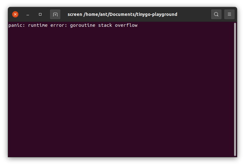
}Do you spot the error in this code, though? I didn't, until this cropped up after a few cycles of the LED:
Googling around found this GitHub issue thread:
 tinygo-org
Oh, look! FPU (floating point units) and my code uses floats! I wonder if that's the cause?
Rather than attaching to the Arduino Uno using GDB or using the -print-stack option (both of which sadly didn't work immediately in my case), I decided to refactor my code to drop floats to see if that fixed the issue.
Partial success there! The stack overflow stopped being printed to the UART. Though the Arduino seemed to silently crash after a while regardless...
I could see when the crash happened too because it would output a TX LED blink the moment it stopped functioning. Yet screen did not pick anything up.
I tried using a different tool for getting output off the Arduino, so I installed socat (Socket Cat). After invoking socat stdio /dev/ttyACM0 with debugging print statements, I noticed this output:
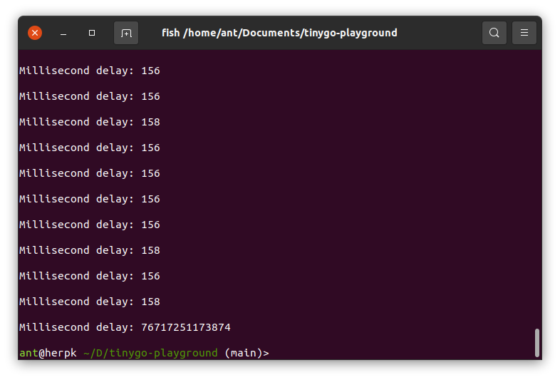
You might say that this is a "development." I might call it a ka-blooey moment.
With the help of debugging with println(), I managed to narrow down the three areas that are suspect:
- Something is going wrong with the conversion from ADC's uint16 result to int64
- Something is going wrong in the channel between the time it gets inserted and read from a separate goroutine
- There's something going wrong with the calculation to convert from ADC value to a "normalised" millisecond count.
All three are possible, though the first two are much less likely. TinyGo is buggy, so it wouldn't be a complete surprise (like not having FPU support), but core features like that are usually more stable.
The third though? I wrote that code, using the best guess of how I wanted to centre my output in a human timescale: normal = 2500 * rawADCValue / 0xffff.
If there's a problem, it's likely in there with the integer division and multiplication.
Here's the final code I settled on, which "worked" well enough:
// Control the pulsing of an LED using a potentiometer and analog input on an Uno
package main

import (
    "machine"
    "time"
)

func main() {
    c := make(chan int64, 1)
    go getInputForever(c)
    blinkForever(c)
}

func blinkForever(c chan int64) () {
    led := machine.D11
    led.Configure(machine.PinConfig{Mode: machine.PinOutput})
    var normal int64 = 0
    var rawADCValue int64 = 0
    for {
        rawADCValue = <- c
        normal = 2500 * rawADCValue / 0xffff // range from 0 to 5 sec period
        if normal > 2500 {
            normal = 2500
        } else if normal < 50 {
            normal = 50
        }
        led.High()
        delayMilliseconds(normal)
        led.Low()
        delayMilliseconds(normal)
    }
}

func getInputForever(c chan int64) () {
    machine.InitADC() // init the machine's ADC subsystem
    input0 := machine.ADC{machine.ADC0}
    var rawADCValue uint16 = 0
    for {
        rawADCValue = input0.Get()
        c <- int64(rawADCValue)
    }
}

func delayMilliseconds(t int64) {
    time.Sleep(time.Duration(1000000 * t))
}
We can see elements of defensive programming now: the normal variable is capped at 2.5 seconds and 50 milliseconds, to prevent absurd output from derailing us entirely.
We've also moved the variables out of the loops, to reduce the amount of garbage collection that needs to go on.
The results are as expected, although rarely the LED will stutter and pulse for a long time when the normal variable goes ka-blooey again.
You can see the variable control at the top of the page, in the video!


